The
analysis phase investigates the “world the application lives in”, its “universe
of discourse” [28] and describes it
in a domain model. To get constraints on this universe and its contents we
follow [36] in
trying to gather some 20 science questions that the application should be able
to answer. The application is here a system consisting of the data model
together with the protocol and implementations. The model will be designed in
such a way that it can contain the required information. The protocol and
implementations must support efficient querying for this information. [36] used this approach
in the design of the SDSS database.
To
create such a list of questions we have contacted scientists with the question
that if they were presented with a database of simulation metadata, what
questions they would want to ask of it to find interesting simulations. The
following list summarises their answer:
- What system/object is being simulated?
- What physical processes are included?
- How is the system being represented in the simulation (particles
(Lagrangian), (adaptive) mesh (Eulerian)), both, other?
- How are the physical processes implemented?
- What numerical approximations were used (e.g. resolution, softening
parameter)?
- What observables are available for the system/object, possibly as
function of time? As it is a spatial system,
at least simulation boxsize, centre-of-mass position.
- What observables are available for the constituents, i.e. what is
the schema of the objects from which the simulation built e.g. particles
in N-body simulation, grid cells in an adaptive mesh simulation or
particle groups in a cluster finder?
- Per snapshot, per simulation object type, per variable:
- Characterise the possible values
- Characterise the result
- Are post-processing results available?
- Are services/applications available for accessing the results?
- Which code ran the simulation?
- Which version of the code?
- Is software available?
- Who ran the simulations?
- What were values of input parameters?
- How were initial conditions created?
- How the results are parameterized?
- Can I access grids of models?
Can I access individual results?
- Which are the inputs
ingredients (usually, which data collections are used?)
- How I can run a simulation?
Can I do it on-the-fly?
- Can I include my simulations
in the VO in an easy way? What I should do?
- Can I compare different
simulations? Can I compare the simulation with my data?
- Which simulations provide
diagnostic tools? (i.e. distance/extinction/quasi-scale free quantities)
- Can I combine the results of
different simulations in a single file adapted for my needs (e.g. own
code)?
The result of the analysis phase
is a model in its own right, albeit rather sparse and schematic. For this
purpose we have built on previous work by adapting the so called Domain
model for Astronomy proposed in [12]. This model forms the basic
structure of the domain model for SimDM, illustrated in Figure 1.
Figure 1 is used in a narrative motivating
the final structure of the full SimDM. We start by assuming the existence of
one or more Files that a publisher thinks may be of interest to the
community because they contain astronomical data. Instead of in files the data
might also reside in a Database, and to be generic we introduce a Storage
base class that abstracts the actual physical location of the data.
Registering that files exist
somewhere is not of great interest without providing information about the contents
of the files. The philosophy that we follow is that the files are of potential
interest because they contain the Results of an (astronomical) Experiment,
and accordingly their contents must be explained by describing the experiment
that gave rise to it. Only in this way can one make scientific use of the files
or other storage resources.
The abstract Experiment is
made concrete by adding some examples of experiment types that are important
for the current model dealing with Simulations and simulation PostProcessing.
In our model, Experiment
represents the actual running of an experiment; to describe the design
of the experiment (the so-called experimental
protocol) we introduce the concept of (experimental)
Protocol. This separation between design
of experiment and the execution is a normalisation
that reduces redundancy in the model. We mirror the concrete subclasses of Experiment
by adding concrete subclasses to (experimental)
Protocol such as Simulator, which represents simulation codes
according to which Simulations are run, and PostProcessor
corresponding to PostProcessing runs.
The (experimental) Protocol class contains InputParameters.
An Experiment using a particular (experimental)
Protocol only needs to indicate the values for these parameters.
In this way a single instance of the (experimental)
Protocol can be reused by many Experiments performed according to
it.
The (experimental) Protocol also defines the possible structure
of the results of the experiments. In our model Results contain one or
more ObjectCollection-s containing Objects
of a given type, represented by the ObjectType contained by (experimental) Protocol. The ObjectType
defines the Properties that these objects have. The Object finally can assign values to these Properties using the ValueAssignment.
For example the results of N-body
simulations may contain particles having properties position, velocity, mass
and possibly others. Adaptive Mesh Refinement (AMR) simulations produce results
that are collections of mesh cells of various sizes, positions and contents.
Similarly post-processing codes such as halo finders produce “halos” and
“semi-analytical” galaxy formation codes produce galaxies.
In general a single result can
contain objects of different types. For example a Smooth Particle Hydrodynamics
(SPH) simulation may contain dark matter particles, star particles and gas
particles. And in general the codes allow one to configure which of these
exactly are chosen in a given experiment.
One aspect of the experiment that is not determined by the
experimental protocol is why the experiment was performed. In the
model we introduce the Target concept for this, which represents real
world objects or processes that are being simulated. For example, with the same
N-body simulator one may simulate a galaxy merger or the evolution of large
scale structure of the universe.
As discussed above, the actual way in which results are stored in
files or databases is hard, if not impossible to model. Instead we assume that Webservices
of various kinds may be used to access the results of simulations.
Some of these will be standardised
in any DAL specification, but custom services may also be introduced. The model
allows one to describe the experiments and their results, which should allow
users to discover results of interest, after which the web services can be
called for actually accessing these.
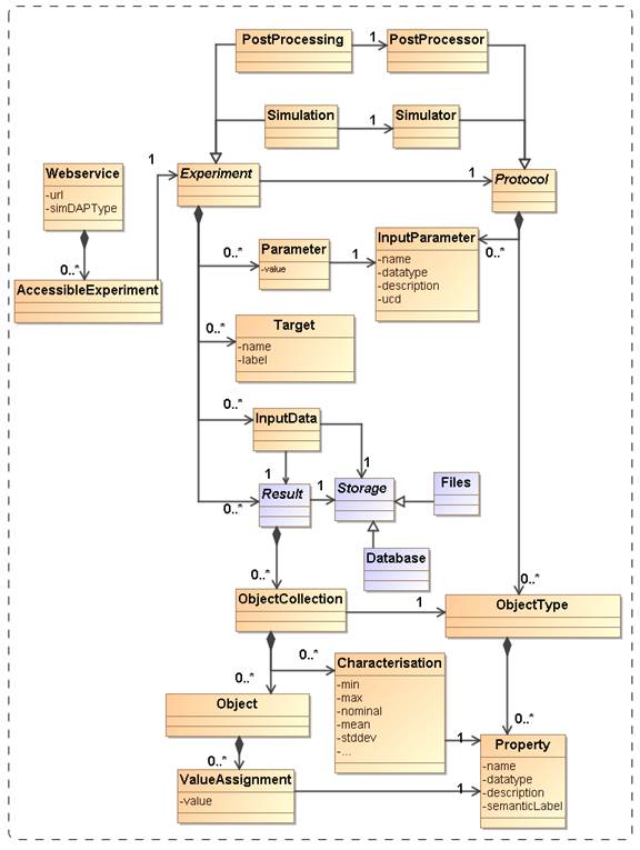
Figure 1: Schematic domain model encapsulating the main design constructs in
SimDM. Elements coloured orange are represented
directly in SimDM, possibly with a different name. Purple elements are not part
of that model, but are used to explain and motivate other features that do
appear there.
SimDM, is a logical model in the
sense of [34] and based on the domain model described in 2.2. SimDM is “logical” in that it aimed to
support an application, namely SimDB, a repository of simulation metadata, but is
still implementation neutral and represented in UML. As a model for an implementation
it is fully detailed. It has a human readable HTML representation which
contains the detailed description of all elements [5]. That document should be consulted for the
details of the model.
Here we introduce the main
concepts and motivate the main design decisions. Where possible we try to add a
hyperlink from a concept’s name pointing into the HTML document the first time
we use the name. The link will consist of a root URL to the location of the
HTML document, followed by a #<UTYPE> that identifies the description of
the actual concept in the HTML document. This we feel is very much in the
spirit of the use cases of UTYPEs. Later references to the concepts will in
general not contain the link. Then class names will be capitalised. Abstract
classes will be in italics. Names of packages, attributes, references or
collections will be preceded by the class name where necessary or it will be
assumed to be clear from the concept what is intended.
For illustration and examples we
use UML instance diagrams rather than XML. See Appendix B.14 for an explanation
of this type of diagram. For reasons explained in section 4.2, serialising this model to XML is rather
complex and would likely confuse the reader rather than elucidate her upon
first reading. XML serialisations can be found in an implementation Note [7] that is produced separately.
UML Packages are subsets of
classes and data types that are deemed to belong together. Whilst not essential
to the model, we have used them to provide some level of modularity. Their main
role is played in the XML schemas derived from the model. Each package has its
own type-schema (see 4.2) which provides a somewhat finer level of
reuse.
The diagram in Figure 2 shows the packages we use and their
dependencies. This hierarchy is reflected in the UTYPEs, see section 4.1. The colours assigned to the packages
correspond to the colours of classes in the diagrams in later sections. The
subdivision in the one parent and three child packages follows the resource class
hierarchy described next.
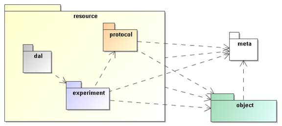
Figure 2: The packages of the SimDM and their relationships. These are
related to each other through directed dependency links indicated by the dashed
arrows.
The SimDM aims at describing
simulations and related concepts. The current model does so with of the order
of 40 separate object types, or classes. Most of these classes themselves
represent parts of other classes. They group together properties or
relationships used in the definition of their “parent”. The composition
relation is used to represent these kinds of parent-child.
But among the classes in the
model there are some that are not used like this. These classes represent
concepts that can stand on their own, are not use to describe part of a larger
concept. These we will call “root entity classes”. In the model they can be
identified by the fact that neither they, nor any of their sub or base classes
are part of another class, a child in a parent-child relation.
These are the classes that
represent the model’s core concepts and their identification is a first
important choice in the modelling effort. In the current model there are actually
two separate collections of classes that are root entities. The Party class represents an individual or organisation. It
is used for indicating who/what wrote simulation codes or ran simulations. The
main focus in this document is on the root entity classes in the Resource hierarchy, illustrated in Figure 3.
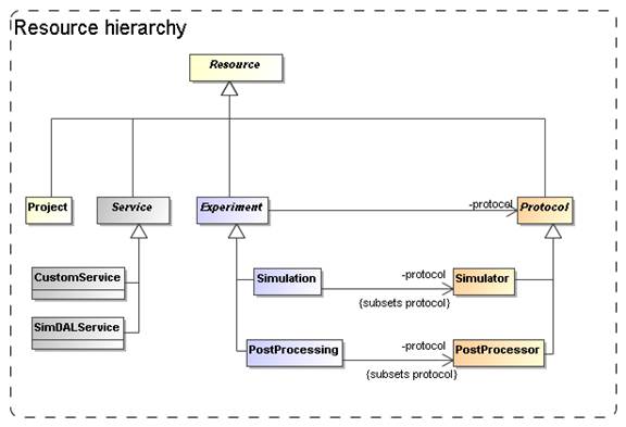
Figure 3:
Root entity classes for SimDM.
From the top down we start with
the ultimate root entity class, Resource, which defines components common to all the main classes. The layer below it
contains Protocol, Experiment, Service and Project. Protocol is the base class of the concrete
classes Simulator and PostProcessor. Experiment is the base class of Simulation and PostProcessing. Service is the base class of CustomService and SimDALService. Project has no subclasses and is concrete.
Our choice for the root entities
follows the domain model in concentrating on the scientific experiments as a
whole. The Experiment class contains, amongst other components, classes
representing the actual results (represented by the OutputDataset class) that people may wish to access. Those are not the core concepts in our model. This
is in contrast for example to the spectrum data model [11] which focuses on the representation of the spectrum, and has the
provenance and other metadata as sub-components.
One reason is that an experiment
can exist without having (yet) produced any results, but to have results (as
defined here) one always needs an experiment. This is a clear example of a
parent-child dependency, where the child’s life-cycle depends on that of the
parent. The standard way to model such relationships is using a composition
relation and that is how we have modelled it. More about the way we model
results below in 3.7.
The separation between Protocol and Experiment is an
important feature that we directly take over from the domain model. This
design was already motivated in Section 2.2 and is related to the Measurement-Protocol
pattern in [27]. That pattern says that when one does a measurement
(of some property) it is important to remember the protocol by which the
measurement was made ([27], p65). In [12] this was extended to experiments, which in
general consist of large numbers of “measurements”, all done in similar ways.
Whereas the term measurement seems to be more applicable to observations, it is
simple to generalise the concept a bit and apply it to the calculation
of properties during a simulation. Actually this is similar to the
CalculatedMeasurement in [27],
An important reason to keep this
separation between Experiment and Protocol also in our logical model is to
avoid having to redefine the parameters and other aspects of a simulation code
each time a simulation is run.
The Service class did not
appear in the original domain model in [12], but we introduced it in the model in 2.2 under the name WebService. In our model it
represents a way to provide access to results of experiments. We could have
tried modelling the way results are stored in files etc., but deemed it too
complex to do so. This is in contrast for example to the spectrum data model,
where we can model the data directly and even can predefine the representation
of the data. There an access reference to the data files can be given to
download a result. For simulations this is in general not possible. In many
cases simulation codes have their particular proprietary formats, often storing
single results over multiple files. Hence we merely allow users to describe
services by which one can access results. Here we only make a separation
between custom services and services following any DAL service specification
that is under construction in the IVOA.
The Project class represents a
scientific project, acknowledging that these in general use one or more experimental
protocols to perform multiple experiments. This class is introduced to allow for
example publishers to group simulations and post-processing runs that were
produced with a common goal. It was inspired by a discussion on whether some of
the SimDM/Resources could be registered as Registry Resources as well. Many of the simulations
registered in a SimDB will not qualify for the same reasons that individual
images do not qualify to be registered. Resources in an IVOA compatible
registry are relatively coarse grained; correspond to archives full of images
published through a SIAP service for example. A Project can be used to define
such collections also in SimDM. And indeed one may wish to register such
collections separately in a registry.
In a data model one can use
aggregations of the corresponding concepts to build such relations. In fact we
have the single aggregation between Project and Resource, providing the
user the freedom to include Service-s and even other Project-s.
The root of the hierarchy of
entities is formed by the Resource class. This class is introduced as a
convenience to hold on to information common to all its sub classes. Its name
is obviously inspired by the Registry’s Resource [13] and it also holds on to curation
information. It “is not a” Registry Resource though in the strict OO modelling
sense. For example it does not inherit all features of that class. But this is mainly
because, as mentioned above, most SimDM Resources will not qualify as Registry
Resources.
3.3 Object types: real and simulated
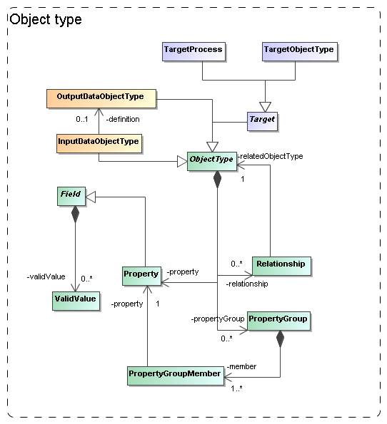
Figure
4: The model needs to describe the types of objects that are being
simulated/used. We model this in quite some detail in a hierarchy of object
types, with properties, grouping of properties and child objects corresponding
to nested objects.
In various places in the
model we need components that allow the user to describe complex (data) objects
explicitly. For example, different simulation codes represent different parts
of the world in different ways. And hence they produce (and use) different
types of data. For example Adaptive Mesh Refinement codes represent a part of
the universe using a grid of cells of varying sizes, whereas a Smooth Particle
Hydrodynamic code uses particles with extent. Hence the Protocol class
needs components for describing the building blocks of the model world it
represents (OutputDataObjectType in Figure 4).
And the same code can often
be used to represent very different types of astronomical objects. E.g. a
particular AMR code might be used to model the internals of a galaxy cluster as
well as a supernova explosion. To be able to describe such objects with some
more detail (say mass of the cluster) Experiment needs a way to describe
physical objects that are produced by a run, (Target ObjectType and -Process in
Section 3.6).
We abstract the building
blocks required to describe such a model world as objects with properties and
relations. In SimDM we support this
with a limited version of an object oriented meta-model, directly inspired by
the UML profile in Appendix B. We add a package object that contains the model
elements that will be used in other parts of the model.
The core concept is the
abstract ObjectType class. An ObjectType
contains a collection of Property-s that corresponds to the
simple attributes used to describe an object. Property is a subclass of Field which defines its main
attributes such as name, description and data type. Also a Protocol’s
InputParameter (see 3.5) is a Field, similar to the way a
VOTable’s PARAM and FIELD share a common structure. In Figure 5 we show an example instance diagram
illustrating the use of OutputDataObjectType (a subclass of ObjectType) and
their properties. A similar diagram could in principle be built for images with
pixels, or AMR codes with grid cells, etc.
Another similarity with the
VOTable structure is the possibility to group Property-s in a PropertyGroup. An example where the
latter may be useful is in grouping all properties related to the position of a
particle, or the chemical abundances of an AMR grid cell .
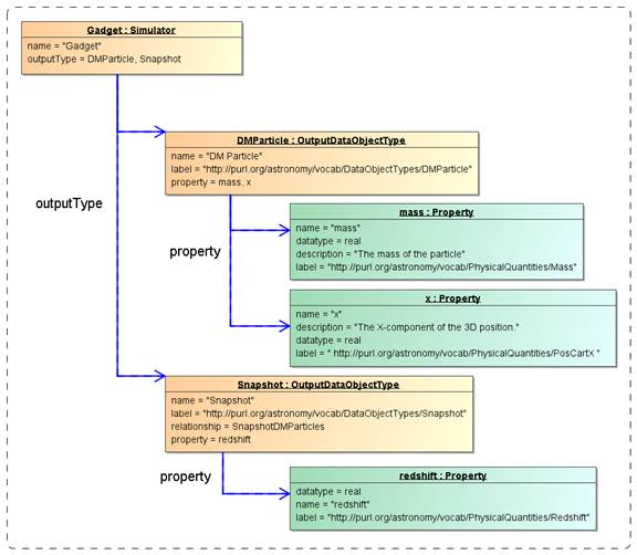
Figure
5 Example instance diagram showing a Simulator with two output types,
"Snapshot" and "DMParticle", each with properties. Note the
SKOS concepts used in the label attributes. These may not (yet) exist in the
corresponding vocabularies.
To describe (hierarchical)
relations between different objects an ObjectType has a collection of Relationship-s, which can be used to
define aggregation, composition or reference relationships between different ObjectType-s.
The instance diagram in Figure 6 shows the same Simulator and output types as
in Figure 5, but adds the relationship of type
“composition” between the types “Snapshot” and “DMParticle”. This relationship
represents the definition of a snapshot as a collection of particles.
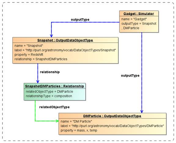
Figure
6 Example instance diagram for an object type hierarchy defined on a protocol.
3.4 Physics, Models and
Algorithms
An important characteristic
of simulation codes is what physical systems and processes can be modelled and
how these are represented in the program. The Simulator class represents
computer codes that create numerical models of the world. Simulators do so by
representing physical processes using numerical algorithms that act on model
representations of real world objects. In our model, see Figure 7, physical processes are represented by the Physics class. It is contained in the Simulator class,
not in the more general Protocol. In effect a simulation protocol is
distinguished from other experimental
protocols in that it models and implements physical processes.
Physical processes are
implemented using particular Algorithms. Algorithms are contained in Protocol, as also PostProcessors
use them. In that case they implement the processing of existing results, and
do not model physical processes. Examples of these are particular algorithms
for extracting clusters from results of N-body simulations.
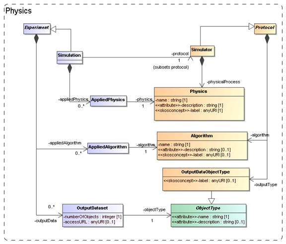
Figure
7: Modelling the representation of physical processes and objects in
Protocols and Experiments.
Finally, experimental protocols need objects
to represent the structure of the physical systems they model. For example,
N-body simulations need particles that represent mass moving around. The model
uses the OutputDataObjectType for this. This class allows
one to define a hierarchy of data objects, from container objects like
catalogues, data cubes or images down to the smallest objects such as particles
or pixels.
A complicating factor is
that many simulation and other theoretical protocols allow users to choose
which physical algorithms to use, or which object types. For example SPH codes
such as Gadget can be run in full hydrodynamic mode, or in pure gravity, “dark
matter” only. Hence, when defining an experiment, users should be able to
indicate the choices they made.
For this purpose Experiment
and Simulation have collections of classes that allow explicit links to the
components they use off the Protocol. The collection of AppliedPhysics references the Physics
used, AppliedAlgorithm the Algorithm and OutputDataSet references the ObjectTypes
used. In contrast to the former two, OutputDataSet has more structure that will
be discussed below.
3.5
Parameters: definition and values
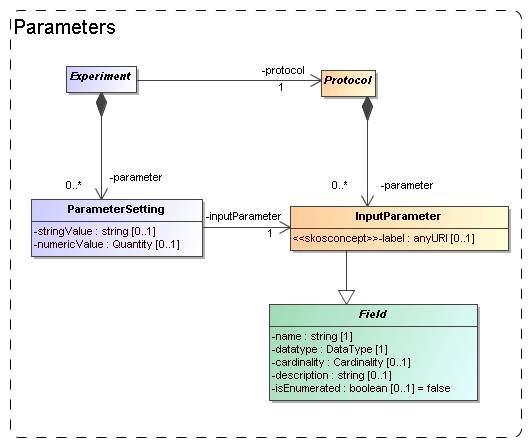
Figure 8: Modelling the parameters: definition under (experimental) Protocol, values under
Experiment.
Software codes generally
require some level of configuration before they are executed. In many cases
this translates into a collection of parameters that must be given values. The
parameters are defined by the code and we model this by an InputParameter class that is contained by
Protocol. Assigning values to these parameters however is the
responsibility of the experimenter and is explicitly modelled as a ParameterSetting class contained by Experiment.
Input parameters are defined
by the attributes name, datatype, label and other properties familiar for example from
the PARAM field in VOTable. Most of these are
inherited from the Field class, which will be
discussed in Section 4.1 below.
Because the details of the
parameter are defined on the InputParameter
class, the ParameterSetting needs
only a pointer (the inputParameter reference) to the appropriate
input parameter and a value. A problem for this model though is what data type
to assign to a possible value attribute. We have no knowledge in advance on the
data type of the input parameter for which a value is set. This is only known
at the instance level, not at the model level. We do not know whether a certain
parameter will be integer, or real, or maybe a string. Our current solution is
to allow two different representations of a value, namely a numericValue, of type real and a stringValue of type string.
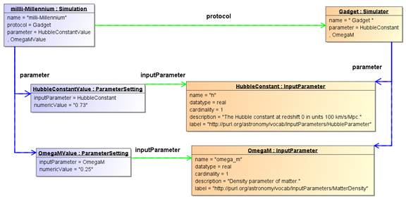
Figure
9 Example instance diagram of parameter definitions and value
assignments.
Figure 9 shows an example instance diagram for
parameter definitions and value assignments. It shows the Simulator “Gadget”
that defines two input parameters: “h”, representing the Hubble parameter and
“omega_m”, representing the density parameter for matter (Ωm).
Note that these parameters have been labelled using the appropriate SKOS
vocabulary. The figure furthermore shows a Simulation run with Gadget (as
indicated by the protocol reference between the objects) which assigned the
values 0.73 and 0.25 to “h” and “omega_m” respectively. Here the inputParameter
references indicate which value was assigned to which parameter. One also sees
the advantage of the normalized design, with the parameter definition separated
from the parameter value assignment: The bulky definition of an input
parameter, with a potentially long definition, need not be repeated; instead it
is reused by every Simulation that uses the same Simulator.
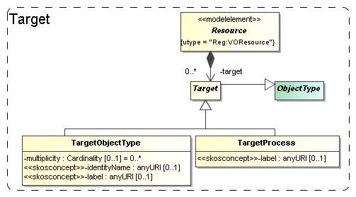
Figure 10: Modelling the goal, or target of a generic
resource as objects and/or processes.
Generally the first piece
of information that the scientists we polled were interested in regarding
simulations was what was simulated.
I.e. what type of object: a galaxy merger, a galaxy cluster, the large scale
structure of the universe? This information in general says something about the
goal that the scientists running the simulation had.
In certain cases the
simulation code itself may completely prescribe the type of objects and
physical processes that are modelled. As example take population synthesis
models such as the Galaxev library, producing spectra of
galaxies.
But many simulation codes
allow many different types of objects to be modelled, and even allow one to
vary which processes are actually modelled. Also in many cases the actual
object that is being simulated is not an intrinsic property of the simulation
code, but is a derived property of the actual simulation. For example an N-Body
code in general does not contain “galaxy particles”. But one can use it to
follow the evolution of millions of low mass particles that are in a particular
configuration that together model a galaxy. But it can also be a globular
cluster, or a filament in the large scale structure.
To cover the concept of the
target of an experiment or protocol, or the goal of a project, we add two
classes, TargetObjectType and TargetProcess. A TargetObjectType
represents an object, or a physical system in the real world, such as a galaxy,
a star etc. TargetProcess represents a physical process such as gravitational
clustering or turbulence. This recognises the fact that some simulations are
run with the goal of investigating a process, rather than producing a model of
a physical system.
Both these classes are
subclasses of Target, which itself is again a
subclass of ObjectType defined in the next
section. Target is contained by Resource so that by inheritance
they are available to all sub classes. We do not model the Target
objects in full possible detail. That we leave to future astronomical
ontologies. We restrict ourselves to a description (inherited from ObjectType)
and a semantic label attribute which identifies the intended
concept using a standardised name from a SKOS vocabulary (see 5.2 below).
3.7 Results: data sets and their statistical summary
We assume users of a Simulation
Database will want to gain access to results of simulations and related
experiments. This is the same as we assume of users of Simple Image Access or
Simple Spectral Access services. For those services the user knows what to
expect, a FITS image in one, a spectrum serialised according to the spectrum
data model in the other. I.e. for those IVOA protocols the object types can be
(and are) predefined as part of the protocol.
This is not possible for
simulations, where we cannot assume to have a priori knowledge about the contents of
their results. Arguably somewhat simplistically one may claim that images and
spectra contain pixels with known properties (space, wavelength, flux). Results
of simulations, even when constrained to 3+1D simulations, can contain as their
fundamental constituents: point
particles, particles with size and structure, mesh cells of fixed or varying
size, Voronoi cells, structured halos, galaxies, radiation fields, galaxy merger trees
etc. And any of these object types can come with any collection of properties:
position, velocity, mass, temperature, chemical composition, entropy etc.
Precisely for this reason users will want to gain knowledge about
the contents of simulation results to decide which simulations might be of
interest to them. Hence the model must support description of the results
explicitly.
Figure 1
illustrates how this is achieved in the domain model: Experiments produce
Results that consist of ObjectCollections of Objects (pixel, N-Body particle
etc) of a particular ObjectType. The ObjectType defines the structure of Object
as a collection of Properties (position, velocity, flux etc), and an Object,
being an instance of the ObjectType, assigns values to these properties. Which
ObjectTypes and Properties are available is defined by the (experimental) Protocol according to which the Experiment is run.
SimDM deviates a bit from this model, for example the separate
Result class is absent and replaced by a hierarchy of object collections. SimDM
also adds a feature to this model that is directly inspired by the Characterisation
Data Model [16]. In many
cases a listing of the actual data objects, using the Object and
ValueAssignment classes would be overkill. For example consider the case of
N-Body simulations. We might define two object types, one representing the
particles, another representing a snapshot, corresponding to the state of the
simulation at a given time. Whereas it might be useful to contain individual
snapshot objects in a meta-data repository of simulations, clearly it is not
useful to list all the particles that make up these snapshots. It might be
useful though to provide some statistics of these collections and just such a
feature we have added to the model.
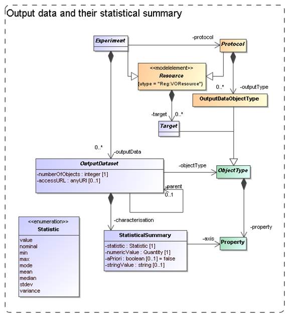
Figure 11: Modelling Output data
sets and their contents.
The model for results and their contents in SimDM is shown in Figure 11. Results
of experiments are represented by OutputDataset-s. As
described in Section 3.2 above, OutputDataset
represents a collection of objects of
a particular ObjectType (indicated by the objectType
reference) produced by the Protocol during the Experiment. In the
typical case the referenced object will be an OutputDataObjectType defined for
the given Protocol. But by referencing the base class ObjectType, an
OutputDataSet may also represent a collection of TargetObjectType-s (see 3.6). Hence
a user has the possibility to characterise the astronomical objects that have
been simulated as well as the more technical objects produced directly.
The OutputDataSet class indicates which types of objects are used in a particular Experiment. The class
contains two collections to provide more detailed information on the actual
results. The first is most straightforward: Users can add DataObject-s to an
OutputDataSet. These represent direct instances (hence data objects) of the ObjectType referenced by
the OutputDataSet. These objects contain PropertyValue-s that
assign values to the Property-s defined on the ObjectType.
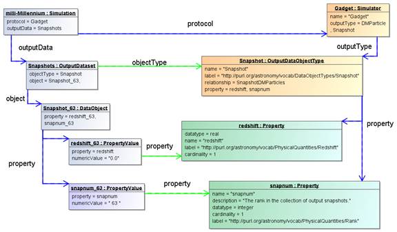
Figure 12 Example instance diagram illustrating the use of the DataObject and
PropertyValue classes.
This part of the model is illustrated in Figure 12 using
an instance diagram. The “milli-Millennium” simulation has an OutputDataset of
objectType “Snapshot”. This data set contains one DataObject, with a
PropertyValue for each of the two Property-s defined on the
OutputDataObjectType: “redshift” and “snapnum”.
The DataObject has collections of ObjectReference and ObjectCollection that can
be used to represent explicit relationships between objects or between objects
and object collections respectively. They implement a Relationship defined on
the DataObject’s ObjectType. An ObjectCollection object links the DataObject to
another OutputDataSet, representing a composition relation. The precise
Relationship that is implemented is indicated by the collectionDefinition reference. Similarly an ObjectReference indicates a reference
relation between one DataObject and another.
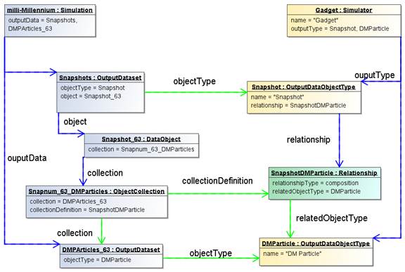
Figure 13 Example instance diagram illustrating the implementation of object relationships
on an experiment's result objects.
This somewhat complex part of the model is illustrated in Figure 13.
The second way to provide more detailed and quantitative information
about object collections is statistical. For many cases a complete listing of
all data objects in an OutputDataSet is not feasible, especially not in a
repository aimed at storing metadata about simulations such as SimDB. But it
may be useful to provide summarising information about the objects in the data
sets.
To support this use case, the model contains the StatisticalSummary class which
allows users to assign statistical values such as a mean or a min/max value to Properties of the OutputDataset.objectType. Which statistic is used is described by the statistic attribute. An illustration of the statistical summary is given in
the instance diagram in Figure 14
.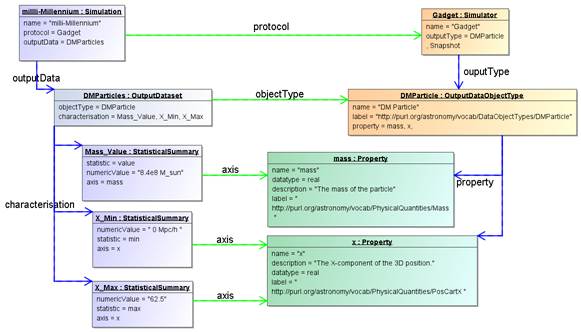
Figure 14 Example instance diagram of characterising a result using the
StatisticalSummary class.
The example shows an OutputDataSet of objectType “DMParticle”. That
object type defines properties “mass” and “x”. The simulation has a dataset of
particles and declares that all particles have the same mass 8.4e8 Msun/h.
It does so by assigning the statistic “value” to the StatisticalSummary object
referring to the “mass” Property. Similarly the min/max values of the “x”
property are declared to be 0/62.5.
Extensions of this statistical summary to more detailed summaries
such as histograms can be easily imagined, but have been left out of the model
as they will have less relevance for discovery, which is the main use case for
the model.
One further feature is important
and is represented by the boolean aPriori attribute. This attribute describes whether
the statistic that is used in the summary is an a priori or an a posteriori
statistic. An a posteriori statistic
is calculated using the results after they have been obtained during the
running of the experiment. For example an a
posteriori mean will likely correspond to the usual expression,
 ,
,
where the  are the values of some property.
In contrast a priori statistics characterise the possible values of the
observables before the experiment is
run. In certain cases a priori
knowledge is available that restricts the possible values that certain
properties may obtain in an experiment. An example is a lower bound set on the
number of particles that a cluster must contain to be included in the result of
a cluster extraction of an N-Body simulation. This can be indicated by a
StatisticalSummary object with statistic=min
and aPriori=true.
Knowledge about the a priori statistics is important in the
interpretation of the results. In the previous example, when interpreting the
mass multiplicity function of a cluster catalogue extracted from an N-Body
simulation, it is clearly important to know what the lower limit was on the
mass of clusters.
In general a priori statistics are the result of, and may often be derived
from the input parameters. However this derivation may not be obvious and will
in general require intimate knowledge of the parameters of a (experimental) protocol. The a priori statistic
may then facilitate the discovery of catalogues that should contain halos of a
certain mass.
Figure 15: The model for (web) services giving access to resources.
The goal of the Simulation
Database is to allow scientists to find simulations of possible interest. Once
these are found the question is what can be done with them. Clearly knowledge
of their existence will be useless if the researcher will not be able to somehow
gain access to the results. The usual way this is done in the IVOA, for example
in the simple image and spectral access protocols, is that the result of a
discovery query contains an access URL that may be used to download the actual
image or spectrum, where moreover the format of the returned resource, FITS,
VOTable or XML document will be known beforehand.
It was perceived from the
beginning even that for the type of simulations that were supposed to be
described a simple download would be unfeasible simply based on the size of
many of the typical N-Body or AMR simulations. This assumption still holds and any
DAL protocol for simulations must be designed to define special purpose
services for retrieving parts of such simulations for example.
Also in the data model we want to
indicate how the relation is between the results and services. This part may be
used in the SimDB specification to allow users to register services and the
Resources they give access to.
In the model the Service class, already introduced in 3.2, represents such access services (see Figure 15). This class can be explicitly linked to
the Resources it gives access to through a collection of AccessibleResource-s. The class has concrete
subclass SimDALService. This represents services
providing access to the results of a limited set of Protocols through a
DAL protocol. The CustomService is introduced so that users can
also publish non-standard services. This part of the model is still rather
summarily treated and may need to be updated depending on developments in the
DAL specification.
According to policies of the data modelling working group, first decided
in Cambridge, 2003, a data model should be presented using a UML diagram, a
corresponding XML schema and a list of UTYPEs. We have created these both using
rules that derive the products directly from the XMI serialisation of the UML
data model.
The original goal of the data model presented
here was to define the structure of a relational database supporting the SimDB specification.
A first draft of a note proposing that spec can be found in [22]. SimDB will use TAP [10] to define the IVOA protocol for
querying this database using ADQL [24]. The results of such queries will
be tabular and serialised as VOTables. Such a VOTable will contain a filtered
subset of the information in the database, but in general in a different form
compared to the structure of the data model. To indicate the meaning of data
elements in such a VOTable, the IVOA has invented the concept of UTYPEs.
A UTYPE is a “pointer into a data
model”. The VOTable XML schema
implements this concept as attributes on various elements, e.g. FIELD and TABLE
and many other elements. The value of such a UTYPE attribute should identify an
element in a data model that is represented by the element itself. For example
a table might point to a class definition in a data model, and a column (FIELD)
to an attribute.
It has become common practice to
provide for an IVOA data model a list of UTYPEs. The Spectrum data model (see [11]) was
the first to add explicit UTYPE-s for each of the attributes in its model and
the Characterisation data model [16] has
followed that example. We follow these examples by assigning UTYPE-s explicitly
to all elements in the model.
Our goal was not to have to make this a separate effort, but if
possible to generate the list of UTYPEs directly from the model. Our goal was
to assign UTYPEs to all identifiable elements in our model and these should be
unique.
To this end we define a set of production rules phrased using the
special names in our UML profile. We have made a guess as to what the format
for UTYPEs will be. In the previous data models a UTYPE was made of a word
consisting of dot-separated “atoms”, similar to UCDs, but without the “;”. We
use a slightly different format to make the distinction between different
syntactic elements from the profile somewhat clearer and also to guarantee
uniqueness of each UTYPE within the data model context. Once (if?) a format is
settled on within the IVOA we will easily be able to adjust our definitions.
The important point we want to make is that it is possible to define
simple rules that can automatically produce unique UTYPE-like words for
all elements of a data model, i.e. the only discussion that may be required is
on the rules for doing so IF a fixed format is preferred (see Norman Gray’s ideas on why this might not be
necessary).
The following BNF-like
expressions define the particular rules we have used for deriving the UTYPEs
from the UML model:
utype := [model-utype | package-utype | class-utype |
attribute-utype
| collection-utype |
reference-utype
| container-utype
model-utype := <model-name>
package-utype := model-utype “:/” package-hierarchy
package-hierarchy := <package-name> [“/”
<package-name>]*
class-utype := package-utype “/” <class-name>
attribute-utype := class-utype “.” attribute
attribute := [primitive-attr | struct-attr]
primitive-attr := <attribute-name>
struct-attr := <attribute-name> “.” attribute
collection-utype := class-utype “.” <collection-name>
reference-utype := class-utype “.” <reference-name>
container-utype := class-utype “.” “CONTAINER”
identifier-utype := class-utype “.” “ID”
For the SimDM these rules produce
a list of UTYPEs for the model. For each model element we provide the UTYPE in
the HTML documentation in [5] and we provide a complete list at the end
of that document. Note also that a URL of the
type
<URL-to-HTML-doc>#<utype>
will link one directly to the
documentation for the corresponding data model element. This is in conformance
with a suggestion made by Norman Gray13.
When representing components of
the data model in a VOTable (for example), these UTYPEs SHOULD be used, in
particular when the VOTable contains results of ADQL queries to a SimDB/TAP
implementation (see SimDB Services).
Alternative views and
representations of the SimDM, for example in any DAL protocol for simulations,
SHOULD use these UTYPEs to refer to elements in the model.
A specification for an IVOA data
model should (must?) contain an XML schema that
defines how to serialise data model instances as XML documents. Similar to the
case of UTYPEs we did not want to make the design of these schemas a separate
effort; instead we want to derive the schema from the model. To do so we have
defined rules for relating XML Schema constructs to our UML model. These rules are
a completion of those described in [37]. It is based also on a view of what such
schemas should look like, restricting the possible set of constructs to be used
in schemas representing data models. These design rules have earlier been
discussed with and accepted by the Registry and VOTable working groups.
We give here only a short
description of these rules. First of all we define two different types of
schemas. First we define “type schemas”, XSD documents containing only type
definitions. For each object type(class) and value type we generate a
corresponding complexType or simpleType. Attributes map to elements of a
corresponding data type (simple or complex), collections to elements of a type
corresponding to the class. References are harder to represent and will be
discussed below.
We next generate a “document
schema” containing root elements. The elements in the document schema define
the valid XML documents one can write and we choose only “root-entity classes”
for their type. That is, only classes at the root of collection trees can be
represented as a document. Fragments of these are not allowed. For example,
only a complete Simulator or Simulation can be represented in a document, not
only a single result, or parameter setting.
Note that this is a choice made
for the Simulation Database service specification. The document schema depends
on the type schemas through XML schema import declarations. This separation
allows flexible usage of the type schemas, for example other services might
make a different choice from the types to serve as valid root elements.
The root schema for the SimDM/XSD
representation can be found here. The type schemas and a
predefined base schema can be found in the same directory and subdirectories of
it. We refer to the SimDB Services
document for more details on the XML schema serialisation and their use in the
SimDB service protocol.
Only the mapping of references
deserves special attention. Our choice of mapping from UML to XSD elements and
our definition of root elements imply that many references must be able to link
between different XML documents. For example the (experimental) protocol reference in an XML document describing an
Experiment must be able to identify a (experimental) Protocol that is defined in a
different XML document. To do this identification we assume we must rely on an
agent that can interpret a serialisation of a reference and use it to look up a
corresponding document. Therefore we map references to elements of a particular
complexType that we define in a base schema. That same schema defines a type
to be used for representing identifiers of objects and the reference
serialisation must be able to reproduce such an identifier.
Further technical details of this
mapping will be described in the appropriate service definition document.
IVOA documents are assumed to
specify dependencies on other IVOA efforts. We have from the beginning realised
that the SimDM effort touches upon various other specifications and general
efforts of other working groups [22]. Here we discuss these relations as far as
they pertain to the Simulation data model.
The correspondence between the
full SimDB specification and the IVOA Registry will be discussed in the SimDB
Service note [22]. Here we will address the relation between
the SimDM and the Registry Data Model as defined in [14].
Figure 16: UML rendering of the Resource complexType from [14].
In Figure 16 we
present a UML rendering of the Resource
complexType as inferred from the Resource Registry VOResource XML Schema [14].
Comparing that model to SimDM/Resource we can see that these two models for
Resource are related, but not identical. In data modelling terms, it is not
true that a SimDM/Resource is a Registry/Resource (or vice versa). Curation is modelled differently and arguably with less detail in
SimDM, but the main difference is in the Content.
SimDM provides a very detailed and specialised model for the Content of Simulations and related
resources, by modelling provenance, motivation and results characterisation.
This higher level of detail gives rise to a higher level of granularity in the
types of resources stored in a SimDB, which in general will be to fine grained
for registration in a Registry. This is similar to the case of a single image,
which is not a Registry/Resource, whereas a SIAP-compatible service, providing access to many
images, is.
A SimDB service itself will have to be registered, i.e. a SimDB
service is a Registry/Resource. In discussion with Ray Plante (IVOA
Interoperability meeting May 2007, Beijing) on this issue it was proposed that
some part of the contents could also be registered in a Registry directly, i.e.
we should be able to identify Registry/Resource-s in SimDB. Considerations to
decide on how to make this identification would be for example that all data
products resulting from a well-defined (and published) scientific project could
qualify. To represent such a possibility for now we have introduced another
subclass of SimDM/Resource: SimDM/Project. This is not much more than an
annotated aggregation of other SimDM/Resources, with some additional attributes
describing the motivation etc. The metadata of a SimDM/Project is not the same
as that of a Registry/Resource, however we propose that we should be able to
define a transformation (possibly implemented again in XSLT) to transform a
SimDM/Project and produce a Registry/XML representation.
In the SimDM, observables, object types,
properties, parameters that play a role in a given simulation have to be
defined explicitly, for the world of simulations is too large to define all
possibilities explicitly in the model itself. This is in contrast for example
to the spectrum data model [11] where we know that a flux is
determined for a wavelength interval, or a model for images where a flux is
determined for a spatial pixel. In principle the publisher of a SimDM/Resource
has all freedom to name and describe these entities. For other users to
understand the meaning of them, we have where appropriate, added an attribute
corresponding to a semantic label. This is similar to the situation in VOTable,
where FIELD-s can be given a UCD (or UTYPE) that allows users to understand the
meaning of a column in the table.
In SimDM we need to generalise
this concept as UCDs are not sufficient for our purpose. For example target
object types are not covered by the list of UCDs and the same for other
elements in our model. The Semantics WG has specified that such vocabularies
should follow the SKOS specification [25]. They have also defined a number
of such semantic vocabularies in the SKOS format, for example of astronomical
objects. We try to anticipate their results by introducing a special type of
attribute in our UML profile that corresponds to a concept in a given ontology.
Technically, in the UML profile we
have defined a stereotype <<skosconcept>> that can be assigned to
an attribute in the UML model. Attributes with this stereotype must define a
value for the tag "broadestSKOSConcept".
The intent of this is as follows
(thanks to Norman Gray for providing the original text with this formal
definition):
<<skosconcept>>
attributes take a skos:Concept as their value. In each case, the value is given
as a single skos:Concept: such attributes may take any skos:Concept which is a
narrower concept than this single typing concept. To be precise, for a typing
concept T, any concept c is a valid value for this property, if either:
c skos:broaderTransitive T
or if there exists a
concept X such that
c skos:broaderTransitive X. X
skos:broadMatch T
This just means that,
if c is in the same vocabulary as T, then it's connected by a chain of any
number of skos:broader, and if it's in a different vocabulary, then there is
some X which is in the same vocabulary as c, with a cross-vocabulary link
between X and T.
In several cases --
particularly those vocabularies which have been created for SimDM -- there will
be a single top concept which everything is narrower than. In other vocabularies -- such as the
AstroObject in the thesaurus version of the ontology of object types -- the
natural typing concept is not a top concept, or is not the only top
concept. This definition also does
indicate that it's legitimate for concept c to come from a different vocabulary
from T: the fact that c has been declared to be narrower than T, either
implicitly or explicitly, is to be taken to be the expression of the vocabulary
designer's intention that this be a legitimate value for this property.
The data model proposed in this document is fully defined in all detail
through a UML model. UML is a large language and we have consciously restricted
ourselves to a subset of the possible modelling elements. We have also added a
few modelling elements using the extension mechanisms UML provides through
stereotypes, tags and predefined data types. This combination of restriction
and extensions is referred to as a UML Profile. The details of our profile are
described in Appendix B.
5.3.2 Characterisation data model
As described in section 3.7, the model allows one to characterise the
results of experiments statistically using the StatisticalSummary class. This
part of the model addresses similar problems for simulations as does the
Characterisation Data Model for observations. We have not followed that model
in detail, but have tried to incorporate its main ideas, giving a new
interpretation to some of these. We believe the best way to
reconcile the two approaches is to see both as specialisations of a more
abstract model defining statistical characterisations of data products. A
proposal for such a “domain model for characterisation was given in [32].
Section 4.1 describes how we generate UTYPEs for the
different elements in our data model. The rules we use to do so have been
subsumed in a draft for a Note on UTYPE-s by [17]. One problem we have with that Note is that
the concepts used in the grammar, and that are direct reflections of syntactic
modelling elements in our UML profile, have not been defined. For models
defined with different UML syntax the grammar does not help.
Our assumption has been that a
UTYPE should allow one to uniquely identify a concept in a data model. We do
not assume that our particular form to do so needs to be taken over. But, as we
describe in 4.1, if
one wants to simply derive a list of unique strings to be associated to
concepts that play a role in data models designed with our UML profile, these
rules may help. Clearly if the syntax were to change we can accommodate that
easily.
The effort on understanding what
UTYPEs really are, how they are to be used, or defined is in our opinion not
completed. But we feel that our approach is compatible with any possible
interpretation, and sufficiently flexible to proposed changes in precise
syntax, were they required.
6 References
[1]
This document, at web address
http://ivoa.net/Documents/SimDM/20120503/index.html
[2]
SimDM
UML diagram obtained from MagicDraw : http://ivoa.net/Documents/SimDM/20120503/uml/SimDM_DM.xml
[3]
A PNG
representation of the main diagram, ‘all’, in the model, extracted from
MagicDraw in
http://ivoa.net/Documents/SimDM/20120503/uml/SimDM_DM.png
[4]
“Intermediate
representation” of the model. An XML document containing all relevant
information from the model in a more readable format than XMI. This document is
generated from the XMI and is itself the source of all other generated
products.
http://ivoa.net/Documents/SimDM/20120503/uml/SimDM_INTERMEDIATE.xml
[5]
HTML
representation of the SimDM in
http://ivoa.net/Documents/SimDM/20120503/html/SimDM.html
[6] XML schema documents derived from the data
model and defining the representation of data model instances in XML. Divided
over various documents. The “element schema” document defining all root
elements can be found here:
http://ivoa.net/Documents/SimDM/20120503/xsd/SimDM_root.xsd . All type schemas can be found in the
same folder, http://ivoa.net/Documents/SimDM/20120503/xsd and sub-folders of it.
[7] Franck Le Petit et al., Implementation of the Simulation Data Model
http://www.ivoa.net/Documents/Notes/ImplementationSimDM/index.html
[8]
Claudio Gheller,Rick Wagner et al, Simulation Data Access
Protocol (SimDAP), http://volute.googlecode.com/svn/trunk/projects/theory/snap/SimDAP.html
[9]
Bob Hanisch, IVOA
Document Standards, http://www.ivoa.net/Documents/latest/DocStd.html
[10]
Pat Dowler, Guy Rixon, Doug Tody, Table Access Protocol
http://ivoa.net/Documents/TAP/
[11]
Jonathan McDowell et
al (2007) IVOA
Spectral Data Model
http://www.ivoa.net/Documents/latest/SpectrumDM.html
[12]
Gerard Lemson, Pat Dowler, A.J. Banday, 2004 A
Unified Domain Model for Astronomy
http://www.aspbooks.org/a/volumes/article_details/?paper_id=861 see also
http://www.ivoa.net/internal/IVOA/IvoaDataModel/DomainModelv0.9.1.doc
[13]
Bob Hanisch et al, Resource metadata for the virtual observatory
http://www.ivoa.net/Documents/latest/RM.html
[14]
Ray Plante et al 2008, VOResource : an XML Encoding Schema for
Resource Metadata
http://www.ivoa.net/Documents/REC/ReR/VOResource-20080222.html
[15]
Carlos Rodrigo et al, S3 : proposal for a simple protocol to handle theoretical data
(microsimulations)
http://www.ivoa.net/Documents/latest/S3TheoreticalData.html
[16]
Mireille Louys et al (2008) Data Model for Astronomical Data Set Characterisation Version
http://www.ivoa.net/Documents/latest/CharacterisationDM.html
[17]
Mireille Louys et
al (2009) Utype : A data model
field name convention Version 0.3
http://www.ivoa.net/internal/IVOA/Utypes/WD-Utypes-0.3-20090522.pdf
[18]
Paul Harrison et al, Simple Image Access
specification Version 1.0
http://www.ivoa.net/Documents/SIA/
[19]
Doug Tody et al, Simple Spectral Access
specification version 1.04
http://www.ivoa.net/Documents/latest/SSA.html
[20]
Theoretical
Spectral Access Protocol
http://www.ivoa.net/cgi-bin/twiki/bin/view/IVOA/IVOATheoryTSAP
[21]
Theory in the VO
G. Lemson and J. Colberg (2003)
http://www.ivoa.net/pub/papers/TheoryInTheVO.pdf
[22]
Gerard Lemson et al (2008) Proposal for a Simulation Database Standard,
IVOA Note 11 July 2008
http://www.ivoa.net/Documents/latest/SimDBTrack.html
[23] Franck Le Petit
et al (2011) Simulation Data Access Layer
(in preparation)
http://volute.googlecode.com/svn/trunk/projects/theory/simdal/note/html/SimDALNote.html
[24]
Inaki Ortiz etal (2008) IVOA
Astronomical Data Query Language
http://www.ivoa.net/Documents/latest/ADQL.html
[25]
Sébastien Derriere et al (2009)Vocabularies in the Virtual Observatory
http://www.ivoa.net/Documents/latest/Vocabularies.html
[26]
Santi Cassisi et al (2008)
Framework for the inclusion of theory
data and services in the VObs
http://cds.u-strasbg.fr/twikiDCA/pub/EuroVODCA/Deliverables/EuroVO-DCA_D11_MPG_Final.pdf
[27]
Martin Fowler (1997)
Analysis Patterns
Addison Wesley Longman, Inc
[28]
Terry Halpin
(2001) Information Modeling and
Relational Databases: From Conceptual Analysis to Logical Design
Morgan Kauffmann Publishers
[29]
XML schema, http://www.w3.org/XML/Schema
[30]
MOF 2.0/XMI Mapping, V2.1.1
http://www.omg.org/spec/XMI/2.1/PDF
[31]
OMG Unified
Modeling Language (OMG UML), Infrastructure Version 2.2
http://www.omg.org/spec/UML/2.2/Infrastructure/PDF/
[32]
Gerard Lemson (2007) Characterisation in the domain
Presentation at IVOA interoperability meeting Bejing 2007.
http://www.ivoa.net/internal/IVOA/InterOpMay2007DataModel/CharacterisationInTheDomain.ppt
[33]
http://en.wikipedia.org/wiki/Conceptual_data_model
[34]
http://en.wikipedia.org/wiki/Logical_data_model
[35]
http://en.wikipedia.org/wiki/Physical_data_model
[36]
Jim Gray et al (2002) Data Mining the SDSS SkyServer Database
http://www.sdss.jhu.edu/ScienceArchive/pubs/msr-tr-2002-01.pdf
[37]
Gerard Lemson (2004) Model Based Schema
PPT presented during Registry video conference 2004-05-13
http://www.g-vo.org/www/uploads/Documentation/Registry_XSD_videocon20040513-14.ppt
[38]
S.
Bradner, RFC 2119: Key words for use in RFCs to Indicate Requirement Levels. http://www.rfc-editor.org/rfc/rfc2119.txt, 1997. IETF Request For Comments.
Appendix A
History
Numerical computer simulations form an increasingly important
component of astrophysical research. Such simulations are used to model
astrophysical processes whose complexity precludes an analytical treatment. The
subject of these simulations includes every possible astrophysical phenomenon,
from the structure of stellar atmospheres, the formation of solar systems, the
structure of galaxies and the description of their constituents, to the
formation of the largest structures in the universe.
The simulations often result in predictions that can be compared to
observations, but in general are much richer, including “observables” that can
only be derived by indirect means from observations. These results can be very
large, rivalling and often exceeding in size the largest observational
catalogues. But they can also be relatively small, consisting of individual
spectra of say a white dwarf, though often in collections resulting from
parameter studies.
The design and execution of these simulations has become a
specialised field of astrophysics, and is these days often performed in large
collaborations. And while it is still true that their results are studied by
these groups only, more and more of these theoretical data are being published
online (see for instance the Appendix B of [26]).
Apart from limited support for publishing theoretical spectra in
SSAP, there is as yet no IVOA standard dealing with the publication of
simulations and their results. In earlier documents we have described the
issues for defining such standards compared to the arguably simpler case of
observational data sets (see for example [21] and [26]).
The proposal for a standard way of publishing simulations was
formulated during a workshop in Cambridge, February 2006. The original idea was
to create an analogue of the simple image access protocol (SIAP, [18]) for
N-Body simulations: SNAP, the Simple
Numerical Access Protocol. During the following interoperability meeting in
Victoria, May 2006, the scope was expanded to include other types of simulation
algorithms, and rephrased to something like “simulations that reproduce
3+1dimensional space time”. It was felt furthermore that not only simulations
themselves should be included, but also certain types of post-processing such
as cluster finders, as long as their results are still aimed at producing a
description of 3D space at one or more points in time. Over time requests have
come in to generalise this scope even more, basically to enable any type of
astrophysical simulation to be handled.
An important change that was decided in Victoria 2006 was that
instead of the SIA protocol, the newer simple spectral access protocol (SSAP, [19])
should be followed as an example. This protocol’s main difference with respect
to SIAP was the explicit data model that was created for spectra and was used
as motivation for the queryData metadata and the getData data format. Hence
SNAP from the beginning had a double focus on a data model plus related query
protocol on the one hand, and a data access and delivery specification on the
other hand.
Shortly before the Trieste interop in the spring of 2008, it was
decided to split SNAP up along these lines in two separate specifications: a
specification for a Simulation Database (SimDB)
which would support searching for interesting simulations and services
providing access to them, and a Simulation
Data Access Protocol (SimDAP) providing a specification for accessing
simulation results.
SimDB on its own is still a rather complex specification. It has
overlap with the efforts and results of many working groups, Data Model (DM),
Registry, Data Access Layer (DAL), Semantics as well as being an integral part
of the Theory Interest Group (TIG). This issue has been discussed in the
Baltimore and Strasbourg interops, as it causes a potential problem for the
standardisation process: an interest group cannot promote a document to a
standard, but which a working group (WG) could do so. It was decided in Baltimore
to postpone that decision by creating a focus group led by the TIG and with
participation form the various WGs.
The current document is the result of a split in original Note that
was written for SimDB. Such a split was proposed to simplify the standardisation
process and after some refactoring was performed mid-2009. This current
document is the first of these and deals exclusively with the data model
(SimDM) and consequently has a natural place in the DM WG. The second document
deals with the use of the data model for defining the model for a relational
database and its related TAP query implementation as well as a service
interface for uploading simulation descriptions to this database. It is not yet
clear whether it can find a place in a single WG.
A parallel effort has been the proposal for a simpler access
standard for small scale simulation, the Simple Self-describing Service
protocol (S3, [15]).
This was a result of an investigation started in the Cambridge 2007
interoperability meeting whether “micro-physics” simulations as they are
sometimes called require special attention. For some time this was covered by
SSA, at least as far as theory spectra were concerned. S3 is actually a direct
reworking of an older Theoretical Spectral Access Protocol [20].
There were questions in the TIG whether S3 might be incorporated in
SimDB and/or SimDAP. In the interoperability meeting in Victoria 2010 the
decision was made that indeed this should be possible. The SimDM was shown to
be able to incorporate the metadata for S3-like services, and indeed proposes
extensions of that. It was decided that the S3 protocol should be merged with
the SimDAP protocol, which from then on will be known by the name Simulation
Data Access Layer (SimDAL).
Appendix B
UML Profile
The Simulation Data Model uses UML as the language for its
specification. This is in accordance with decisions of the IVOA data model
working group. One advantage of UML is that it is implementation neutral. It is
a graphical language, consisting of “boxes and lines” that is very suitable for
whiteboard discussions but allows one to model the concepts and relations in a
static data model. It is also rich enough to allow one to describe all
important data elements and relations.
In fact, UML is almost too rich. It is easy to become overwhelmed by
the large number of possible syntactic elements to choose from for modelling a
particular structure. Luckily UML allows one to formally define a subset of its
language where one restricts oneself to a subset of the syntactic elements.
Such a subset is called a UML Profile.
Apart from creating a more restricted language, a Profile also allows on to
assign new meanings to existing elements by defining stereotypes with
associated properties (tag definitions). It is also possible to predefine classes
and data types (see below) that can be reused by the data modeller.
In our modelling effort we have
defined an initial implementation of a UML profile as created by MagicDraw. The
profile is contained in the
UML file containing the SimDM data model. Here we give a list of the main
elements that we use and give a short motivation for their inclusion in the
language. It is our opinion that the DM working group should be ultimately
responsible for a profile such as this, as it gives the possibility of defining
a domain specific language for all IVOA data modelling efforts, thus giving some uniformity to those
disparate efforts.
B.1
Element
All
elements mentioned below are specialisations of UML Element.
Stereotypes
·
<<modelelement>>: This
stereotype can be assigned to any UML Element
and is used to define the utype tag
on.
Tags:
o
utype [string]: this holds the actual UTYPE that points to
the other modelling element that is represented here.
B.2
Model
This
is the root of the complete model, contains all packages, classes etc. Also
contains any imported profile.
Stereotypes
·
<<model>>
If the designer wants to annotate the model
with the tags in this stereotype (s)he must explicitly associate this
stereotype to the Model.
Tags:
o
author: Indicates the author(s) of the model.
o
title: provides a long title to the model. The name of the model is assumed
to be short.
o
subject: 0..* list of subjects in the sense of the Registry’s subject attribute.
B.3
Package
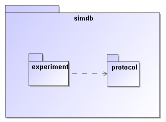
Figure 17: This figure shows a package
"simdb" that contains two other packages. Of these the experiment
package depends on the protocol packages, which is indicated by the dashed
arrow. See Figure 2 for the somewhat more complex
package structure used in SimDM.
A package groups
related elements such as class definitions and possibly sub packages. Packages
can depend on each other (indicated by the dashed line), which means that
elements in one package can use elements in the target package in their
definition. This relation is transitive. A package is similar to an XML
namespace and in fact we map UML packages to XML namespaces in the XML schema
mapping for the model described in 4.2.
B.4
Class
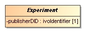
Figure 18: A Class is a rectangular box,
with the name of the class in boldface.
Classes are the fundamental building blocks of
a data model. A Class represents a full-fledged concept and is built up from
properties and relations to other Classes. An important feature of Classes as
opposed to DataTypes (see below) is that instances of Classes, i.e. objects,
have their own, explicit identity. That is, we want to assign an explicit
identifier to each particular usage of this concept, for instance here to
distinguish between various Experiment instances.
Properties:
·
isAbstract
Indicated by italicised name of the object. Implies that no instances
can be made of the class, only of concrete (=non abstract) sub classes.
B.5
ValueType
A ValueType represents a simple
concept that is used to describe/define more complex concepts such as Classes.
ValueType-s are, in contrast to Classes not separately identified. They are
identified by their value. For example an integer is a value type; all
instances of the integer value 3 represent the same integer.
In this profile ValueType-s are
only represented using specialised examples.
Attributes (see below) must
have a ValueType as their datatype.
B.6
PrimitiveType
PrimitiveTypes
are the simplest examples of ValueTypes. They are represented by a single value
only. A set of PrimitiveTypes is predefined in the IVOA profile (see Figure 19).
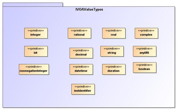
Figure 19:
The PrimitiveTypes that are predefined in the IVOA profile.
B.7
DataType
Figure 20: Example of a structured
datatype:Pos3D represents a position in 3D space and is defined using x, y and
z attributes. The DataType symbol is distinguished from the Class by the
<<dataType>> stereotype.
A DataType is a ValueType that has more
structure than a single value. This structure is modelled using Attributes,
just as on ObjectTypes.
B.8
Enumeration
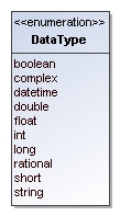
Figure 21: An enumeration is indicated by a box with the name of the enumeration
and the list of valid literals.
An Enumeration is a ValueType that is defined by a list of valid values.
These are the only values that instances of this data type can assume.
B.9
Attribute
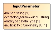
Figure 22: An attribute is indicated by a line with a name, a datatype, an
indication of the multiplicity and possibly a stereotype.
An Attribute is a
Property of a type (object type as well as structured data type). An
attribute’s data type is always a Value type, not an object type. For object type
properties one should use a Reference.
Properties
·
data type
·
multiplicity/cardinality: indicates the
cardinality of the attribute (assumed to be 0..1, or 1. This is a relational
bias based on normal form and the assumption that most databases do not allow
storage of arrays in single columns.)
·
Stereotypes
·
<<attribute>>
To assign further properties such as the tags this stereotype attribute must be
explicitly assigned.
Tag definitions
o length
[integer]: Constraint indicating that an attribute must have a specific fixed
length. Is relevant only for attributes of type string.
o maxLength
[integer]: Constraint indicating that an attribute may at most have the
indicated length. Is relevant only for attributes of type string. Is used in
mappings to TAP to indicate the length of the corresponding column. Thist would
seem to be very much an application specific feature and therefore belong to
logical modelling. But this profile can be used for that purpose, hence it is
included.
o uniqueGlobally:
Constraint indicating that only one instance of the type of the Class owning
this attribute can have a given value. Globally should be read to mean globally
in a given instance of the model, i.e. a database for example that stores
instances of the model.
o uniqueInCollection
[boolean]: If true, indicates that the value of the attribute cannot be shared
by the same attribute of any other instance of the Class owning this attribute
that is in the same collection, i.e. has the same container object. In SimDB/DM
an example is given by the name attribute of the InputParameter class for a
given Protocol.
·
<<ontologyterm>>
There are many instances in the data model where we need to describe elements
of the SimDB/Resource-s explicitly, because we do not have implicit information
based on the context. Examples are the various properties of object types, the
target objects and processes etc. Apart from a name and a description we then
frequently add an attribute which is supposed to "label" the element
according to an assumed standard list of terms.
We model this using the <<ontologyterm>> stereotype. Attributes with this stereotype
are assumed to take their values form such a predefined "ontology".
Tag definitions:
o ontologyURI
A URL locating a standard (RDF|SKOS|OWL|???) document containing a list of
terms from which the value for this attribute may be obtained. It is our
opinion that the Semantics working group should be responsible for the
definition of relevant ontologies (or semantic vocabularies, or thesauri, or
...) required for a given application domain, though the contents should be
decided in cooperation with domain experts.
B.10
Inheritance
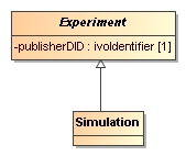
Figure 23: Inheritance is indicated by a line with an open arrow from a subclass
to its base class.
Indicates the typical “is a” relation between
the sub-class and its base-class (the one pointed at). In this profile we do
not support multiple inheritances.
B.11
Collection
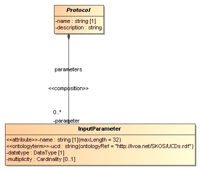
Figure 24: The line with the filled diamond on one end and an arrow on the other
indicates a (parent-child) composition relation, or collection, between the parent,
on the side of the diamond; and the child, on the other side.
This relation indicates a composition
relation between one parent, container object and 0 or more child objects. The
life cycles of the child objects are governed by that of the parent.
In UML a composition relation is represented
by a binary association end.
B.12
Reference
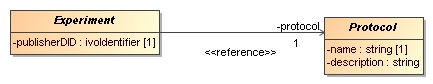
Figure 25: A Reference is represented by a line connecting a class with another,
referenced, class with an arrow on the referenced class. Note, the
<<reference>> stereotype indication is not required.
This is a relation that indicates a kind of
usage, or dependency of one object on another. It is in general shared, i.e.
many objects may reference a single other object. Accordingly the referenced
object is independent of the "referee". In our profile the
cardinality cannot be > 1.
For implementing the Reference in UML we use
a shared, navigable binary association end.
B.13
Subsets
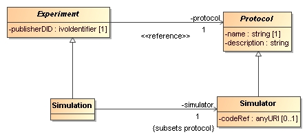
Figure 26: The subsets property can only be assigned to a relation between two
objects that are both subclasses of Classes that have an equivalent relation.
It is indicated by the {subsets ...} annotation to the relevant association
end.
The “subsets” property, when associated to a
Reference or Collection (in UML to the corresponding association end),
indicates that a relation overrides the definition of a relation of the same
name defined on a base class. It does so by specifying that the target class at
the end point of the relation should be a subclass of the target class at the
endpoint of the original, sub-setted relation.
B.14
Instance diagrams
In the
text we provide examples of instances of the UML model using instance diagrams.
An example is the one shown in Figure 27.
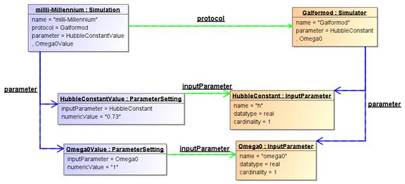
Figure 27 Instance diagram
example.
Boxes represent objects, i.e. instance
of a particular class. The name of the class is indicated in the header after
the colon. The name before the colon is simply an identifier of the instance.
The lower part of the box shows properties and their values. This includes both
attributes and collection and reference relations. The latter are also
represented using directed links between the related objects. Blue links
represent composition relations, green lines reference relations.
The diagram therefore represents the
following situation:
A Simulator named “Galformod” is
defined with 2 parameters, “h” and “omega0”. These both have data type “real”
and cardinality “1”. A Simulation was run using this Simulator as indicated by
the “protocol” reference between the two objects. The name of the simulation is
“milli-Millennium”. It assigned values to the parameters, 0.73 to “h” and 1 to
“omega0”.
More complex
instance diagrams are shown in various places in the text. All are snippets of
the full example which is summarised in the next Appendix.
Appendix C
Issues
We identify and discuss here
several issues with the SimDM that need to be discussed further.
C.1
Normalisation
The current version of the SimDB/DM is rather more normalised
[9] than most of the other data models in the IVOA. We explain this concept
based on a particular choice we made during the modelling process, and then we
discuss the consequences of particular choices.
Figure 28: Non-normalised model for experiments and parameters.
At an earlier stage, the model was less normalised in the design of
the input parameters of an experiment, as is illustrated in Figure 28. There was no
separate protocol class, only an attribute protocolName on the Experiment
class indicated the protocol by which the experiment was run. Also, the input
parameters on the experiment were completely contained in a collection of Parameter-s.
The Parameter class contained all the details, including name of
the parameter, description, ucd etc. It also contained the value
of the parameter in the experiment.
Figure 29: Normalised modelling of experiments, protocols and their
parameters.
Currently the model treats parameter definitions and settings as in Figure 29. In this
normalised design, the Protocol is given a class of its
own, and it contains the input parameter collection. The InputParameter class
does not contain a value, only the definition of the parameter:
name, datatype, ucd, description. The values
assigned to parameters in a given experiment are captured with the ParameterSetting
class, contained in a collection of Experiment.
The motivation for this change of model was that a SimDB instance
will in general contain many simulations (experiments) run with the same
simulator code (protocol). In the old model, each experiment has to define the
collection of input parameters with all details. In the new design this only
has to be defined once, on the appropriate protocol. This clearly is less
redundant, which is one important design goal of a normalised modelling
approach. At the same time it provides an explicit identity to input
parameters, which allows us to ask explicit questions about all parameter
settings for a given, identified parameter. In the old model this is only
indirectly possible, using equality of the name of input parameters for all
experiments having the same protocolName. Now we can ask for all
experiments with the same protocol reference, and look for parameter settings
with the same input parameter reference. This is arguably a more
"correct" model of reality.
There are therefore advantages to normalisation, but there are also
disadvantages. We need to realise these and make choices that optimise the
usability of the data model. One of the main disadvantages is that references,
which naturally have to be introduced when normalising a model, are more
difficult to deal with than most of the other modelling elements, particularly
in some physical representations (see below). When defining a new experiment,
one will have to find the input parameter that one needs to set, and instead of
simply giving name/value, one needs to represent the reference to the
parameter. For this one may have to extract the protocol as stored in the SimDB
and find the appropriate identifiers of the input parameters. In this sense an Experiment
definition becomes less self-contained. It depends on the details of the registered
Protocol.
This protocol is registered separately and necessarily at an earlier point in
time.
This puts strong requirements on SimDB implementations to maintain
referential integrity, something which will be even harder to achieve if we
were to allow cross-SimDB referencing. In one advanced usage scenario the UC
San Diego version of SimDB registers the Enzo simulator, whilst the Italian SimDB allows registration of simulations
that used it and reference the remote protocol.
Similarly a query language needs to be able to handle with this
level of indirection. For example in a relational database one needs to write
joins between ParameterSetting and InputParameter. For expert SQL users this is
not a problem, but is something to get used to. For simpler query languages,
those not allowing joins, like TAP/Param, asking meaningful queries becomes
very difficult. One way around this problem could be to add some view
definitions to the model. In relational databases, views are predefined, named
SQL queries that can be treated as if they were tables when querying the
database. It is quite straightforward to define some SQL queries that as it
were denormalise the model and put the input parameter definition back under
the experiment together with the value. This way one may protect users of the
database from the high level of normalisation.
C.2
Quantities and Units
At various
locations in the SimDM data model numerical values can be defined, for example
in parameter settings or the characterisation of properties of representation
object type collections. Often these numerical values will need to have a unit.
The IVOA has two ways of dealing with units. Either units are fixed explicitly for
properties/parameters in protocol or data model, sometimes depending on the
small list of possible UCDs. Alternatively units are explicitly stated, for
example in VOTable. At the moment we support the second mode, especially
because, as is true for VOTable, we do not know what kind of property is being
used. To this end we introduce a value type in the model, Quantity,
which contains a value and a unit, and which is the data type of various value
attributes, for example in NumericalParameterSetting
or Characterisation. In the XML
schema this is translated to a complexType
with 2 elements, in the relational database schema to two columns, one with the
value, and one with the unit. It is in the use of the relational schema that we
anticipate problems with this approach, especially in the query protocol to
SimDB. Consider the typical science question: return all N-body simulations
with particle mass roughly 1010 Msun. In SimDB this would
be need to be translated in an ADQL query which contains the unit column
explicitly. Allowing users’ freedom of registering SimDB resources using any
units they desire can lead to resource containing, for the same observable
"N-body particle mass", values with a whole range of units. To
provide reasonable support to users requires the SimDB implementation to be
able to do the automated transformation. We propose in SimDB to use ADQL/TAP as
the query interface. If units are stored explicitly users can phrase queries
using these.
An
alternative approach is to mandate stating values for properties with a given
UCD (or other semantic label) always with the same units. This would solve the
query problem but poses others. For one it may be very (too?) unnatural for
users to be forced to use meters for cosmological simulations, or megaparsec
for simulations in the solar system. Related to this is the probably
contentious discussion of what units to assign to what UCD. One might choose SI
or cgs units, but these are not always very useful or natural.
C.3
Linking services, experiments and other resources.
Compared to the Domain Model discussed in 2.2,
the Simulation Data Model proposed here lacks concepts
representing the storage of results.
The reason is that whereas we can define the concept of a Result as collections
of Objects quite satisfactory, we have shied away of trying to model the
precise way these results are actually stored in files or a database. There are
simply too many possible and actual ways in which results can be stored in a
file system. In general, a result, or snapshot in our model, cannot be modelled
with a simple reference to a file or table in which it is stored. Large results
may be split up over many files, stored as structures, or in arrays. We have
therefore decided not to open this can of worms (or reopen it, see the Quantity
data model http://www.ivoa.net/internal/IVOA/IvoaDataModel/qty23.pdf).
Instead we assume the existence of web services that allow users
access to the results of SimDB experiments. Some of these services may
implement a standard protocol as defined by SimDAL, or they may be custom
services. The precise way to relate experiments to services and what can be
inferred about how to call them is the task of the SimDAL protocol.
In the model actually web services are related to resources in
general. This can be used to represent services that gives access to a set of
experimental results from some project, or that can for example visualise any
result of experiments performed according
to a fixed protocol, for example generic Gadget-format visualisers.
